THE 21st CHESAPEAKE SAILING YACHT SYMPOSIUM
ANNAPOLIS, MARYLAND, MARCH 2013

A Refinement of the Methods Used to Determine the Balance of a Sailing Vessel during the Design Phase, with Application to Sail Design and Subsequent Sail Selection and Sailing Operations
Capt. Iver Franzen, Iver C. Franzen & Associates, Annapolis, MD
ABSTRACT
The thrust of this paper is, first, to attempt to define the relationship between the individual sails, both together and separately, and the hull with somewhat more precision, and secondly, to develop a calculation tool to better establish this relationship, and to better anticipate the vessel's over all sailing behavior. Because of those factors that effect balance including and beyond those addressed by the traditional design approach as taught by most current texts on sailboat balance, the need for the factor "lead" will never go away. However, by including, as will be demonstrated, an additional balance factor, specifically the longitudinal sheet positions, into the balance equations during the design phase, sailboat balance can be predicted with better accuracy. The primary objective of this refinement will be the ability to design sail profiles, especially the complement of headsails, which will result in the least (adverse) change of balance when changing from one headsail to another, and which can be applied to either new designs, or to existing boats in need of out-of-balance remedies. This would mean that each anticipated sail combination can be analyzed for its lead, and therefore adjusted during the design phase to insure that proper helm is maintained from one combination to the next.
NOTATION
AR Aspect Ratio = luff²/SA, per sail, averaged
AWA Apparent Wind Angle
AWS Apparent Wind Speed, knots
CEg Center of Effort, geometric
CEd Center of Effort, dynamic
CD Drag Coefficient
CL Lift Coefficient
CLP Center of Lateral Plane
CLRg Center of Lateral Resistance, geometric
CLRd Center of Lateral Resistance, true dynamic
D Aerodynamic Drag
GM Metacentric Height
GZmax Heel Angle of Maximum Righting Arm
L Aerodynamic Lift
LOD Length on Deck, ft.
LWL Length Waterline, ft.
SA Sail Area, sq.ft.
S/VBP Sailing Vessel Behavior Prediction
TWA True Wind Angle
TWS True Wind Speed, knots
V Boat Speed, knots
VDC Vertical Distance between CLRg and CEg
VPP Velocity Prediction Program
WHSR Wind Heel Stiffness Ratio = AWS²/Heel Angle
ρ Air Density, .0024 lb sec2/ft4
Δ Displacement, pounds
φ Heel Angle
INTRODUCTION
A number of well-known design texts, papers, and dissertations have over the years addressed that aspect of yacht design pertaining to the balance of a sailboat, and in so doing have made it clear that it's, well, not clear, to the extent that, in spite of this extensive and valuable work, establishing a proper "lead" for a given design requires either an exhaustive, exhausting amount of calculation, or reliance on educated guesswork to estimate the lead. Numerous influences on a sailboat's balance include, but are not limited to her tenderness or stiffness; her keel and underbody profile; her beam, draft, and displacement relative to her length; the fullness of her lines, especially forward; the aspect ratio of her rig and whether she's a single- or multi-masted rig; even the age and condition of her sails. And, of course, that she will be expected to sail properly in a wide variety of conditions further complicates her designer's efforts to correctly and accurately determine her "lead."
Most competent sailors understand the concept, function and, indeed, the importance of balance on a sailboat. And that understanding, even if only visceral, generally extends to most of the various ingredients and factors that result in good balance. The traditional approach to determining balance during the design phase, however, typically concentrates only on the geometric relationship between the centers of effort (CEg) of the sails themselves (and including only the generic foretriangle instead of individual
headsails) relative to the center of lateral plane (CLP). The attempt to apply this traditional design approach to balance within the operational realities of achieving good balance in a variety of conditions has therefore made it necessary to arrive at a specific lead for a given boat only by estimating within a broad range known by experience to be successful for that boat's genre. This has led to a number of out-of-balance designs requiring adjustment, and sometimes significant surgery, after sea trials.
One variable not previously discussed, however, is the position of the longitudinal sheeting positions, i.e., where on the boat does the sail, by way of the sheet, actually transfer all or part of its load to the boat? What effect might this sheeting position have on balance? And, once that sail's position of influence is more accurately determined, what improvements to, or new procedures for, the prediction of "lead" might be possible?
BACKGROUND
Years ago, the author was delivering a 38' cruising sailboat from the Virgin Islands to Newport, Rhode Island, and, a few days into the passage, found himself in building winds and seas. Nothing alarming, but time to shorten sail. In changing from a genoa (about 140%) to a working jib (about 80%), he suddenly found that his previous weather helm had not only eased, but had actually become a slight lee helm. Some years later, this experience repeated itself on a different boat. The larger genoa was replaced with a smaller working jib, and the helm changed from weather to lee. Given the teachings discussed above, perplexing. Back at the drawing board, these two situations were drawn up roughly from memory and investigated from the point of view of comparing the various actual sail plans to the boats' underwater profiles. Design method leads were within the ranges one would expect. Taking the actual sail shapes involved, the smaller headsails coupled with their respective mains resulted in CEgs farther aft than those based on the larger headsails. Again, as one might expect. Yes, heel had been reduced which would explain some lessening of weather helm, but certainly not to the extent experienced. Given that the balance leads had been effectively shortened with a smaller jib, the expectation was for a small increase in weather helm, which in turn would hopefully be eased again by the reduction in heel due to reducing power. Such, however, was not the case. Having considered all the other variables that might have had a bearing on these situations, the only remaining variable that could explain this dichotomy was the sheeting positions themselves, and how they might change the geometry of balance.
THE GEOMETRY OF "LEAD"
Figure 1 shows a typical balance diagram, variations of which have been in our lexicon for decades. To review, the area of the foretriangle is used to geometrically determine the generic CEg of the headsail(s). This CEg is combined with the geometric CEg of the mainsail (and other sails if applicable) to determine the CEg of the entire sailplan, and indicated on an outboard profile drawing. The CLP of the underwater profile of the boat is also geometrically determined, and shown on the same drawing. The longitudinal positions of the CEg and the CLP are compared, and the horizontal distance between them, i.e. the lead (balance lead), is expressed as a percentage of the waterline length. As we know, CEg is with very rare exception always ahead of CLP.
One should be reminded here, well explained by numerous texts and papers, that a distinction exists between CEg and CEd, or dynamic CE. A similar distinction exists between CLP, a geometric measurement, and CLR, the dynamic position of the center of lateral resistance as a boat is sailing. In both cases, these dynamic positions move forward of their parent geometric positions when sailing, the magnitude of their movements depending on many variables such as wind speed, angle of attack, depth of draft of the sail, longitudinal position of that draft, depth of keel, length of keel, cross-sectional shape of the keel, shape of the leading edge of the keel, etc. Since these dynamic positions are constantly shifting depending on conditions at the moment, it's therefore impossible to rely on these positions as arbiters of balance. But, since they both move forward more or less concurrently, their "lead" approximates that of the geometric lead, therefore justifying the continued use of CEg and CLP to estimate the boat's lead, especially in the design phase.
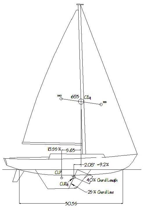
Figure 1 – Typical Balance Diagram
Having said that, an additional refinement to the CLP can and should be applied. Since this discussion is concerned primarily with upwind sailing, the CEg of the rig can remain in play. However, since the CLR moves forward of the CLP immediately upon forward motion, regardless of point of sail, then an establishment of its position must be made in order to better establish the relationship between the sails and the hull, and to address helm considerations to be discussed in depth below. A geometric version of this CLR position, shown on Figure 1, has been well established by a number of experts as lying on a "vertical" chord line of the keel 25% aft of the leading edge of the keel, and 40% down from the waterline to the bottom of the keel. (The forefoot and the rudder are considered as offsetting each other.) Since other factors influencing its longitudinal position (Monk moments, leading edge shapes, etc.) can move the CLR in either direction, this geometric position of the CLR (henceforth, the CLRg) will be taken as the most useful tightly estimated point from which to formulate the following analyses.
MODIFIED GEOMETRY OF "LEAD"
Figures 2a & b – Balance Diagrams for Actual Sails
Figure 2a is a balance diagram showing the geometric lead, in this case with the actual genoa headsail shape coupled with the main. Figure 2b shows the balance and lead condition with a reduced headsail. While departing from using the generic foretriangle, both are otherwise based on the traditional means of establishing CEg. It can be seen that, as the headsail is reduced in size, the overall sail plan CEg moves very little. Until now, this has in part been a justification for using the generic foretriangle as the headsail portion of the balance diagram. However, if the sail area is considered as coupling with the lead dimension to create a moment, then the lesser moment with the smaller headsail should theoretically have, in the anecdotal situations above, allowed the bow to round up more readily, i.e., a greater weather helm.
However, the sails, especially the headsails, do not impart their load upon the boat directly under the CEg of that sail, as the traditional balance diagrams suggest. If the sail were to be sheeted to a position on the boat directly below its clew, such as a club-footed staysail, then yes, such would be the case. However, all other headsails by necessity have their sheets led a certain distance aft in order to maintain proper tension on both foot and leach. The magnitude of this distance is based primarily on the height of the clew above the deck. All sailors have experienced the dynamic loads on these sheets. The next step then is to incorporate some representation of these loads into the geometry of lead.
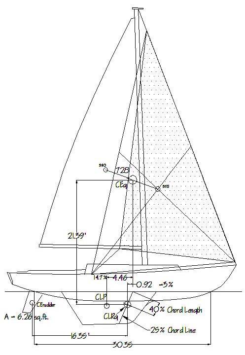
Figure 3 – Modified Balance Geometry, #2 Genoa, 100%.
Figure 3, based on the same boat and sail plan as Figure 2, proposes a geometric method for doing this. First, it requires that the generic foretriangle be abandoned, and that the actual proposed headsails be worked with instead. On the drawing, indicate a given sail's sheet and where it meets the deck (the sheet position). (Authorities vary as to the exact angle the sheet should travel from the sail. Some say to bisect the angle at the clew, others to split the difference between this bisector and the line from the sail's CEg to the clew, still others say to start at a point on the luff 40% of the hoist up from the tack and draw a line from that to the clew, the extension of which is the sheet. The right answer for a given sail is generally somewhere in between these variations, which will more closely coincide with higher clews and lower aspect ratios.) Once the sheeting position is located, draw a triangle the corners of which are the head and tack of the sail and the sheet position (ignoring the clew). Find the geometric center of this triangle in the normal fashion. This now becomes that sail's CEg, which will more closely approximate its actual influence on the boat. When coupling this sail with the rest of the sail plan (main, etc.) to establish the overall CEg, continue to use the sail's actual area, but with this modified position of its center of effort.
APPLICATION TO EXISTING VESSELS
Figures 4 and 5 represent a fairly close approximation of the arrangements described in the anecdotes above. In the Figure 5 arrangement, the helm stayed slightly lee until about 18 knots of wind, above which it went weather. What becomes apparent is that this sailing vessel example, which showed a traditionally derived lead of 18%, now, with its #1 genoa, and accounting for the inclusion of the sheet's influence on the boat, shows a lead in Figure 4 of 14.3%. If the same modified process is applied to Figure 5, with the smaller headsail, then a lead of 14.9% is arrived at as shown. This is contrary to the virtually unchanged lead when using only the sails themselves to determine the lead.
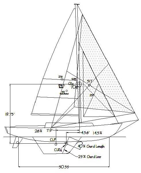
Figure 4 – Sail Plan of the boat described in the anecdotal example, in this case with her #1 genoa.
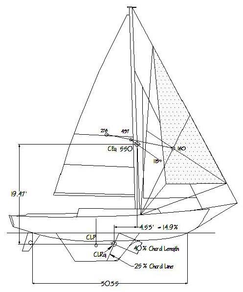
Figure 5 – Modified Balance Geometry, small working Jib
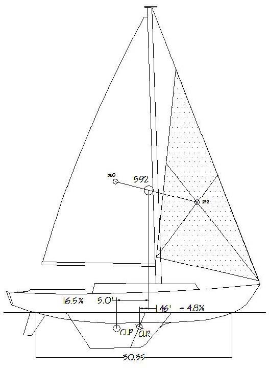
It is perhaps now becoming apparent as to why, in the experiences described above, the smaller headsail induced a lee helm. Simply put, the sheet position for the smaller headsail was too far forward, creating a balance lead that differed significantly and detrimentally from that derived from the genoa. The correction for this vessel then, if it is assumed that the balance was correct for the genoa (i.e., the full sail plan), is that any smaller headsails should have profiles which, with their sheet positions included, would generate a similar or lesser lead. In this case, this would be accomplished by reshaping the smaller headsails with higher clews in order to move their sheet positions aft. Figure 6 shows how this might take shape, in that a small working jib of an area similar to the small jib in Figure 5 is reshaped with a higher clew so as to move the sheet position aft significantly. The resulting balance lead is 12.6%, less than the genoa's 14.3%, resulting in a reduced sail plan that continues to maintain acceptable balance, such that, while the helm still stays lee in light air, it becomes weather at a more useful lower wind speed of about 14 knots, or about when you'd want to reduce sail.
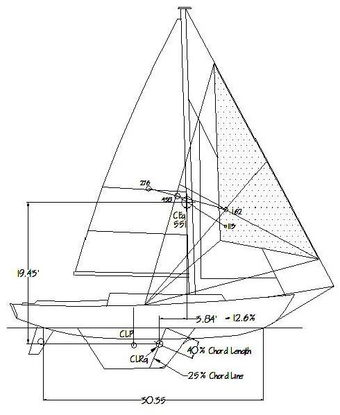
Figure 6 – Reshaped small working jib to correct lead and helm.
As a further illustration of how this approach might be applied to correcting an existing boat's performance, let's look at the case of a 31' fractionally rigged racer-cruiser whose weather helm with her 160+% genoa was annoyingly excessive. The clew of this sail was not particularly high, but high enough to put the sheet position quite far aft, at about the .8LOD position. The owner of the boat, however, was particularly enamored of this sail, most likely due to the magnitude of the financial investment therein. After being the last boat at the windward mark with discouraging consistency, the crew rebelled, and insisted that the #2 jib be tried next time out. Next race (wind about 10kt), first to the mark, first to the finish line! In addition to quicker, more efficient tacking, this 110%, fairly low clewed, full hoist sail put its sheet position quite a bit farther forward at about the .5LOD position. Applying the modified geometry described above, this sail increased the boat's balance lead and lessened the weather helm significantly. The foot came off the brake and the boat was allowed to sail as intended. Of course, lessening the heel helped as well, while still keeping plenty of power. The big genoa was still useful as an off-the-wind sail, so the owner was not entirely bereft. But the #2 became his #1 windward sail.
APPLICATION TO NEW DESIGN
Therefore, if the primary headsail's contribution to the overall balance has been determined by design or proven by experience to be correct, and can therefore be taken as the "baseline" lead, then, by shaping all other headsails such that their sail+sheet position geometry yields similar or lesser balance leads, good overall balance should be easier to maintain throughout the suit of sails. It will appear that lead dimensions will be smaller using this method. But, if the boat sails properly with the slight weather helm known to produce the best windward performance, then so be it, these numbers might become our new benchmarks.
This presents a new problem, however. If the effort is to establish a single indicator of how a boat is going to balance itself, as the traditional approach presently does, then having a distinct dimensional lead for each headsail is counter to that. To further investigate this issue, an additional factor must be introduced into the modified lead calculations. This was hinted at above in the discussion of Figures 2 and 3, but without the benefit of accounting for the effects of the sheeting positions. Now that those effects are being included, the idea of considering lead as a moment rather than a dimension becomes more important. For example, looking again at Figures 5 & 6, lead moments of lead x SA (assuming the same wind pressures for both) further confirm the adverse helm change with that particular smaller headsail. Even with this it will be necessary to approach this as a range of moments for a given boat, since we're dealing with multiple sail combinations, rather than a single foretriangle, making a new single indicator for the entire sail complement difficult. It might be possible, however, to minimize the magnitude of this range such that a firm sense of overall balance can be achieved, especially with the primary headsails.
If the idea of balance is to compare the effects of competing entities, then the lead moment must be considered as offsetting another moment for this to have meaning. Since the lead moment is one which is meant to be a falling-off moment, it's function then can be seen as offsetting a rounding-up moment, or, more accurately, offsetting most of that rounding-up moment, since a small amount of it is considered beneficial. And the best indicator that the amount of residual rounding-up moment is correct is the amount of rudder angle required to offset that moment while keeping the boat on the most favorable windward course. The generally accepted range of optimum effective rudder angles to offset the rounding-up moment, while providing lift with minimum drag is 3-5 degrees. Therefore, part of the design process is to design the sails in such a way that the rudder angle for a given set of sails and conditions can be determined, as closely as practical. Then, if excessive weather or lee helms are calculated for a given sail combination within the range of wind strengths anticipated for that combination, then sail profile shapes and their associated sheet positions can be modified as necessary.
One good way to test this application is to look at an existing boat considered by all to have been a very successful design. One such boat is the Cal 40, by C. William Lapworth, and for which he designed a full complement of headsails. Figure 7 is a simple profile sketch of this boat, showing both her traditionally derived lead of 18.5% relying on geometric centers only, and her lead of 9.2% based on her CEg as relating to her CLRg, or the geometrically derived CLR as discussed above.
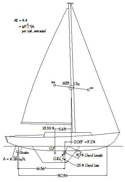
Figure 7 – Profile of the Cal 40, showing traditional
lead determination both from CLP, and from the CLRg.
Also shown is the steering arm.
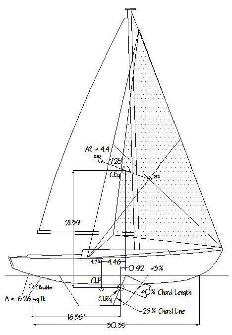
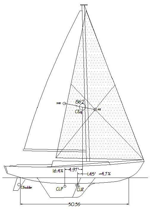
Figure 8 – Cal 40, full main, #2 jib, moderate air, showing the Leads.
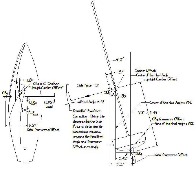
Figure 9 – Determining the Lead dimension and the Transverse Offset dimension of the sail plan shown in Figure 8.
The concept of solving for rudder angle to determine the final balance condition will require that the two competing balancing moments, Lead (Falling Off) and Luffing (Rounding Up), which can also be thought of as torques, be determined beforehand. First, for the arm components of these moments, the positions of the CEg and the CLRg relative to each other must be determined both horizontally and vertically, including accounting for the heel of the boat. Referring to Figures 8 & 9, the fore and aft Lead dimension between CEg and CLRg is shown in the normal fashion on Figure 8 and on the plan view of Figure 9. Also required is the total transverse offset of the sail plan, or the distance that the CEg is moved laterally off of the centerline due to both the camber/sheeting offset and the angle of heel. The range of these offsets, and the force components of the two moments in question will then be determined by the . . .
S/V BEHAVIOR PREDICTION (S/VBP) TOOL
With a few additional assumptions, sufficient and proper information is now available to utilize Figure 11 below, the S/V Behavior Prediction Tool spreadsheet, developed by the author for this paper. A typical condition calculated for is shown in Figures 8 and 9 above, and demonstrates the derivation of certain of the pre-entries required prior to final calculation, such as the lead dimension, the vertical distance between CLRg and CEg (VDC), and the initial camber offset sheeted close-hauled. Additional foundation information required includes displacement, metacentric height (GM) derived from previously established stability information, sail area, beam, and main foot length (E). Also required will be rudder area and rudder arm, taken from the rudder's CEd to the CLRg.
A plot of various curves, an example of which is shown below in Figure 12, will be created based on the output of these calculations. These curves will be plotted against a range of true wind speeds at a given apparent wind angle, in this case 30º.
The assumptions for the specific Figure 11 calculation are a) apparent wind is 30º; b) AR-related lift and drag coefficients and their associated ratios are derived from numerous sources and averaged into the Table B matrix
as shown on Figure 11, c) boundary layer considerations will be ignored, and d) performance information has been established either by VPP or by underway experience, and indicated in Figure 10.
In the S/VBP Tool, first enter, from condition parameters and from Figures 8 and 9, the following: TWS and AWS in knots, primary (reference) SA, actual SA for the condition being tested, AWA, GM, LWL, rudder area, rudder arm, VDC, horizontal distance CEg-CLRg (Lead), and the aspect ratio (P[or I]² / SA) per sail, averaged. Additional manual entries from prompts in the spreadsheet are: upright offset factor, lift coefficient, and Drag-Lift (D/L) ratio.
The subsequent calculations first yield the profile drag heel angle and the resulting effective sail area. Table A in the S/VBP tool shows righting moments against heeling moments per degrees of heel. The pertinent φ used in the subsequent calculations is taken from the coincidence of the two moments for a given wind speed. Righting moment is taken as Δ times GM (in this case estimated, as actual hull lines and stability information is unavailable) times φ. Heeling moment is wind pressure at the given AWS times the SA adjusted for heel times the VDC adjusted for heel.
Table B indicates the lift and drag coefficients to be used, in this case parametrically estimated, which then yield the lift and drag forces, which in turn, by way of the standard forces/vectors diagrams shown, yield the angle between the lift and the resultant. Since lift is now known, the resultant is calculated. The angle between the resultant and the side force is now determined, which, along with the resultant, are used to calculate the thrust. That same pair of factors now also yields the side force. To this horizontal side force is added a downlift /downforce adjustment in the form of: sine² of the profile drag heel angle, times the side force. This Adjusted Side Force, together with the Thrust, comprise the forces that will be applied to the Lead and the Transverse Offset respectively to arrive at the Falling Off and Rounding Up moments. These moments can, and perhaps should, also be considered torques.
The transverse offset is then calculated. The upright camber offset is determined by diagram as shown in the plan view of Figure 9, or by a predetermined fraction of the beam. This upright offset is then multiplied by the cosine of the heel angle to arrive at an adjusted camber offset. This is added to the offset caused by the boat's heel, which is found by multiplying VDC by the sine of the heel angle. The sum of these two offsets is the total transverse offset, based on the profile drag heel angle. Since the adjusted side force is greater than the profile drag, the profile drag heel angle is adjusted accordingly, becoming the side force (Adjusted) Heel Angle. This adjustment is applied to the transverse offset, becoming the Adjusted Transverse Offset. It is the outboard end of this transverse offset arm upon which the thrust force acts, thereby creating the Rounding Up moment/torque.
Now that the Lead has been more precisely measured by incorporating the sheeting position and confirming the CLRg, and the side force established, multiplying one times the other yields the Falling Off moment/torque.
These two opposing moments/torques can now be compared as shown, specifically by subtracting the Falling Off (Lead) Moment from the Rounding Up (Luffing) Moment to arrive at the Residual Steering Moment. A positive result indicates a weather helm, a negative result a lee helm. The magnitude of this residual moment needs to be offset by a similar steering moment in order to hold a desired course, which in turn, assuming the range of steering moments vs. rudder angles has been established as shown on Figure 11, yields the effective rudder angle required, in this case at 4º.
A distinction needs to made here between effective rudder angle and actual rudder angle. Since a boat sailing to windward will be making a certain amount of leeway, the water flow approaching the rudder will not be parallel to the boat's centerline. Generally speaking, the angle of that flow into the rudder, the downwash angle, will be about half the leeway angle. If the leeway angle is often approximately 4 degrees, then the downwash angle will be about 2 degrees, and can be used as the correction for most normal sailing situations. Therefore, if the effective rudder angle is 4º, then the actual rudder angle will be 6º.
At a true wind speed of 10 knots in this case, the resulting effective rudder angle from the calculations in Figure 11, at 4º, is essentially optimum. Considering the gradually increasing draft of aging sails, this is a good starting point, although something closer to 2.5-3º might be even better with new sails. Of note is that the modified method dimensional lead, at 3%, is very close to the main/genoa arrangement at 2.8%. Given that the #2 jib most closely approximates the foretriangle, one might consider this condition to be her benchmark condition. For a racer-cruiser like this boat, having this primary sail with a foot you can see under and not scoop water, while still low enough for good racing performance, is just right. For a true racer, this foot might be closer to the deck, with the rest of the CEg/CLRg/steering geometry designed such that similar results to Figure 8 are still achieved. The larger #1 can then be tailored to be a true deck-sweeper. For a world cruiser, a #2 with a slightly higher foot/clew might be advisable, with the rest of the configuration designed accordingly.
Two items should be noted at this point: First, The HM derivation, described above as part of Table A, of wind pressure at the given AWS times the heeled SA times the heeled VDC is essentially the same as the HM = HM0º x
Cos²φ used by several regulating authorities. This construct is presently under review (Johnson, et al, 2013), especially for higher heel angles (>GZmax). This S/VBP tool may need to be modified accordingly as this research progresses. Second, that this sail plan has been calculated up through winds much stronger than would normally be carried by this plan, as shown in the graph in Figure 12. A by-product of this S/VBP Tool may then in the future be the ability to also predict behavior when the boat is in extremis, not only in terms of both heel and helm response, but also downflooding. However, since neither lines nor stability information are available in this case, the effects of heel angles beyond GZmax have not yet been incorporated into the S/VBP Tool. GM in this case has been parametrically estimated.
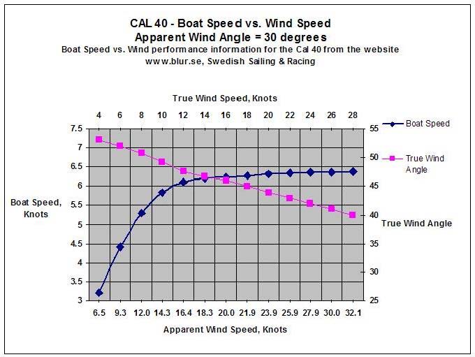
Figure 10 – Performance data for the Cal 40 sailing to windward, assuming 30º apparent wind.
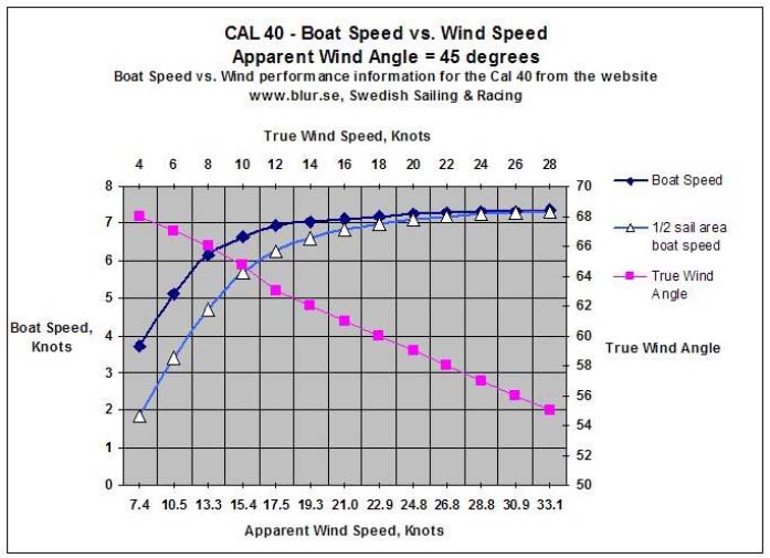
Figure 10a – Performance data obtained from www.Blur.se, showing estimated adjustments for
50% ± reduced sail, and sailing with 45 degrees of apparent wind.
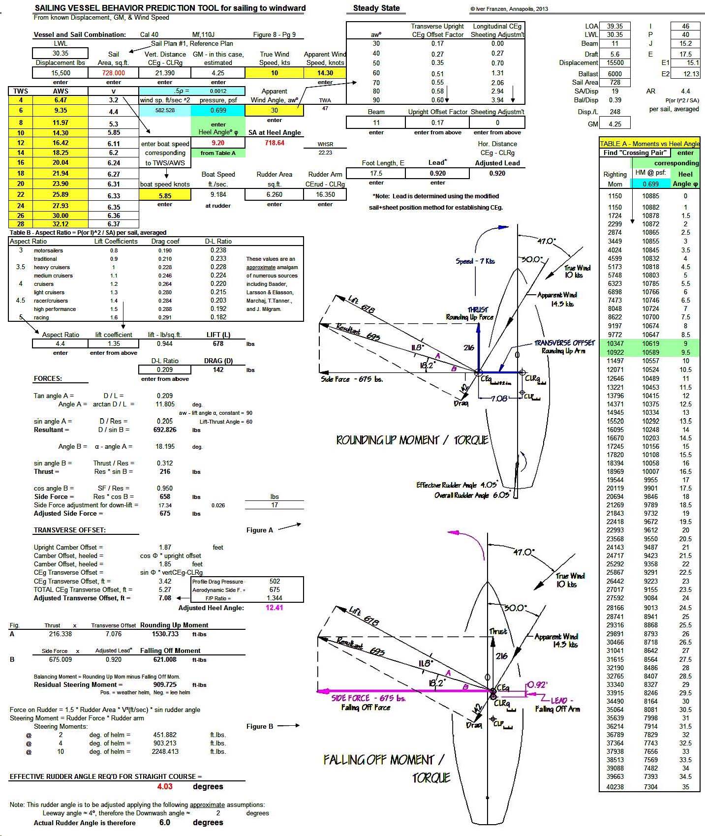
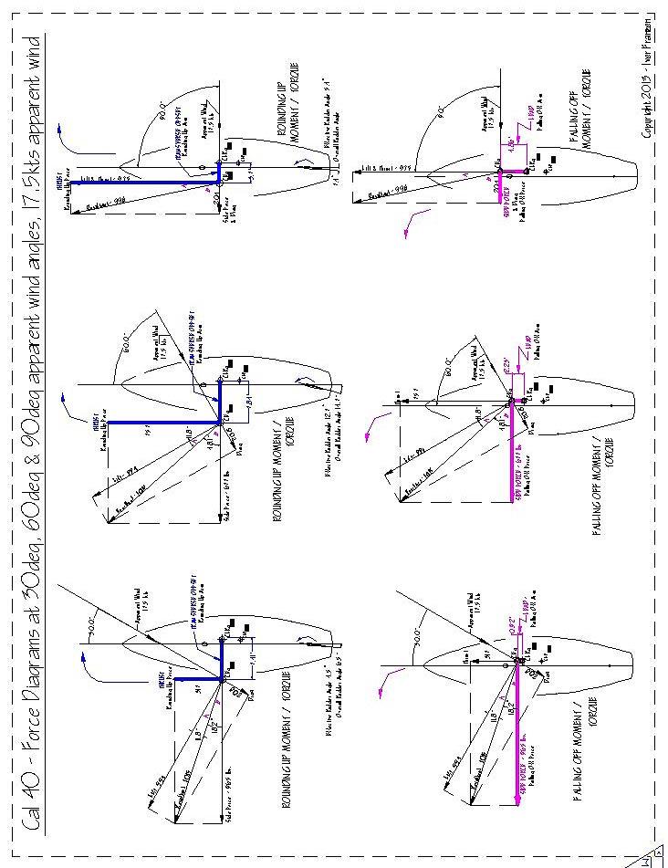
Figure 11 - Construction of the Rounding Up (Fig. A) and Falling Off (Fig. B) Moments (Torques), in addition to the
calculations to determine her Residual Steering Moment, and, finally, the rudder angle needed to hold a steady course. See also the Appendix for additional Rounding Up & Falling Off Moment/Torque constructions for other upwind points of sail.
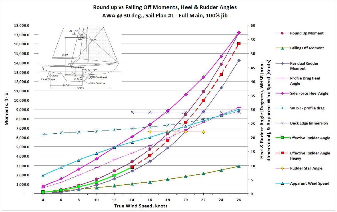
Figure 12 – Graphic Results derived from the S/VBP calculation procedures in Figure 11, Sail Plan #1, the reference plan.
Figure 13 shows the Cal 40's S/VBP curves with her genoa. Applying the modified balance geometry shown above and the balance/helm calculations now results in very light to moderate weather helm up to about 10 knots of wind, becoming heavier to handle in the 12-15 knot range, as one would expect for full sail. Experience has taught that weather helm in light air is generally very minimal, and occasionally becomes a tolerable lee helm. This condition is confirmed here. In extremis situations also now become more apparent.
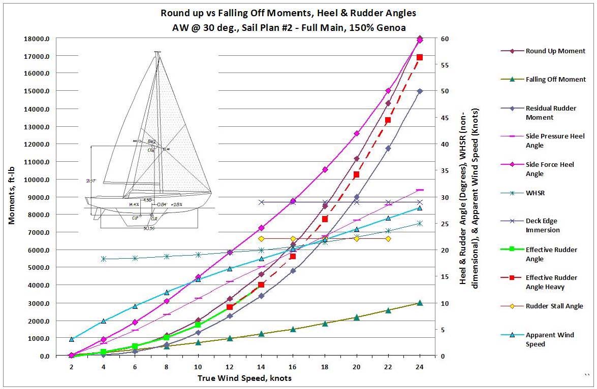
Figure 13 – S/VBP results, Sail Plan #2, Full Sail.
As the wind freshens, shortened sail configurations at 45º apparent wind are shown in Figures 14 and 15. It is interesting to compare these two configurations, as they have somewhat similar sail areas, but Figure 14, Plan #6, is showing a double reefed main with a working jib, while Figure 15, Plan #8, has a single-reefed main with a storm jib. Their balance leads are 3.34' (11%) and 0.04' (0%) respectively, a significant difference. As might be expected, the weather helm for Plan #8 starts to get heavy fairly early at around 15-17 knots of wind. Plan #6, on the other hand, is keeping a reasonable helm until about 22-24 knots of wind, which most would consider preferable in these conditions, even at the expense of a lee helm at winds less than 12 knots.
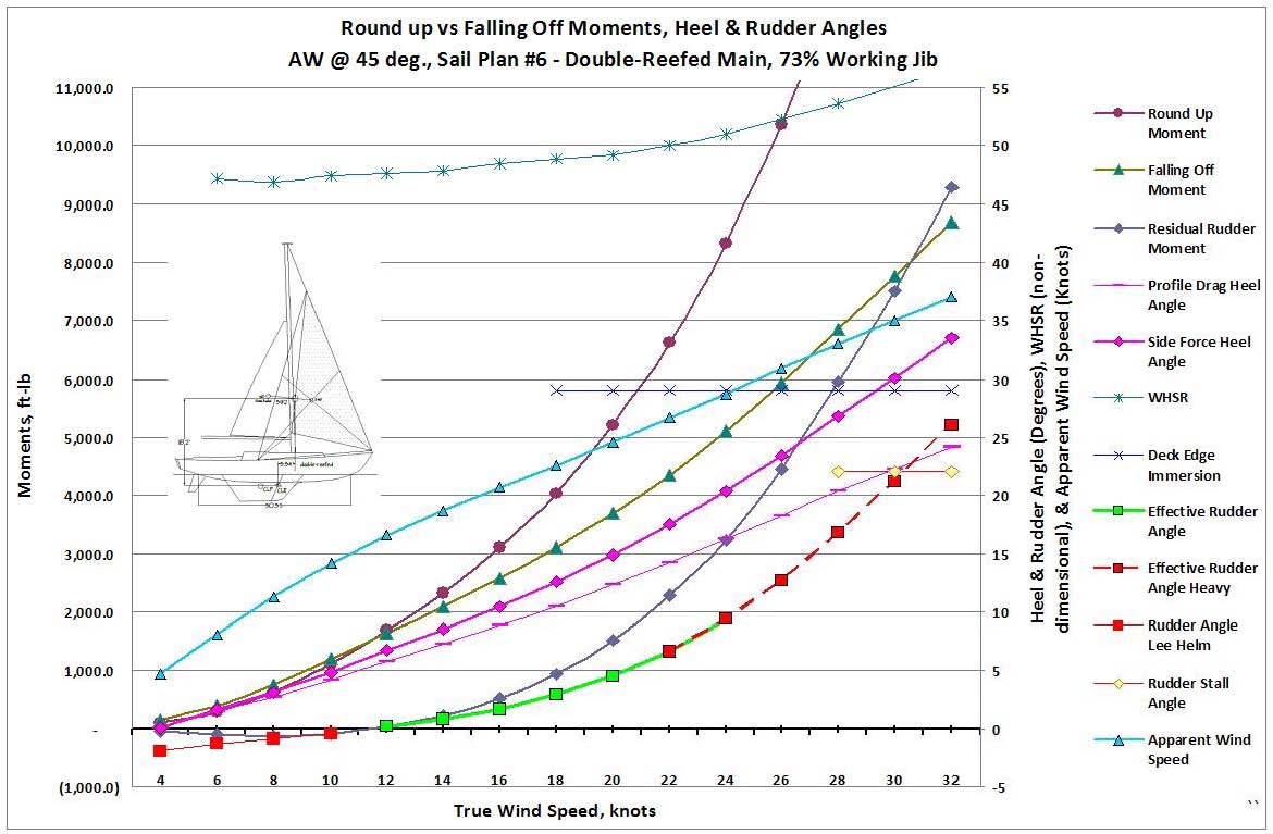
Figure 14 – S/VBP results, Sail Plan #6, double-reefed main & working jib.
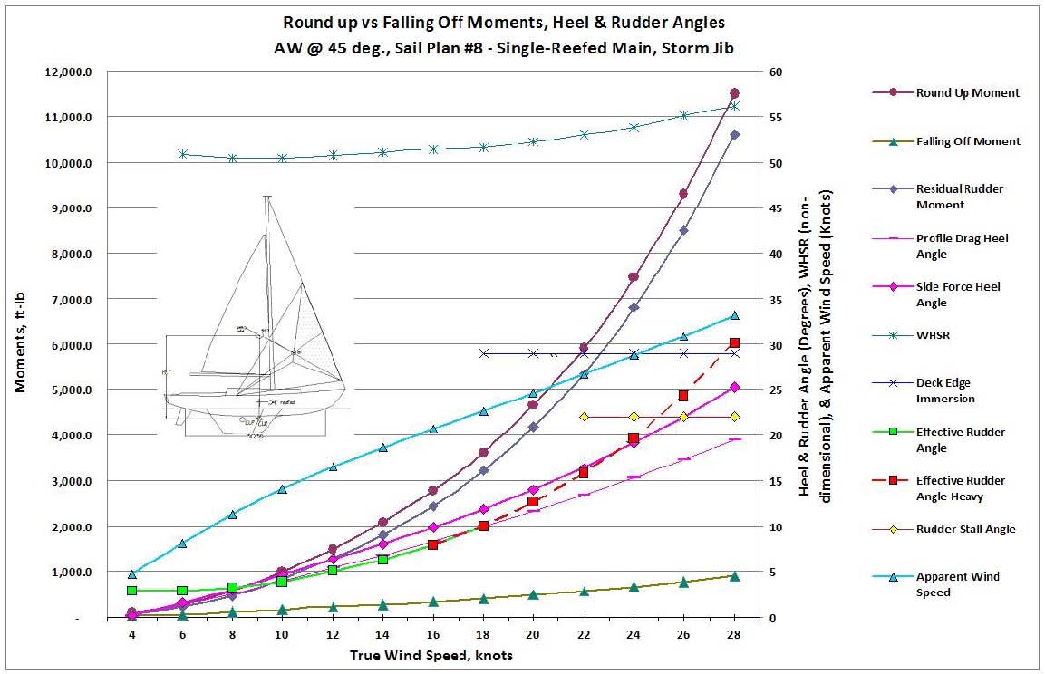
Figure 15 – S/VBP results, Sail Plan #8, single-reefed main & storm jib.
It is also interesting to note, however, that, while Plan #6 exhibits better helm behavior than #8, it also heels about 8-10% more than #8. Granted, the sail area for #6 is about 10% greater, but its VDC is about 5% less. So, yes, in this case the proper lead has everything to do with keeping a better helm, even in spite of a very small disadvantage in heel.
For purposes of calculating these reduced sail scenarios, the boat speed information shown above in Figure 10a is adjusted downward assuming the sail area is reduced by approximately half, and whose approximation is shown in that Figure by the curve "1/2 sail area boat speed."
By the way, getting back to the anecdotal situation in Figures 4 & 5, applying the S/VBP Tool to the full sail arrangement, including sheets, Figure 4 yields an optimum weather helm of about 3º in moderate conditions. But, as suspected, the smaller headsail (low clew, forward sheet position) actually reduced that helm to less than half, even in stronger conditions. (That it didn't go to a lee helm in the S/VBP as experienced is most likely due to the author's inadequate memory of the details of the boat's actual configuration.) As also suspected, when calculating for a small higher clewed jib (sheeting farther aft) of the same area, the resulting weather rudder angle increased back up to almost 3º. Clew height and sheet position do make a difference.
The consistency of good balance results shown here throughout the Cal 40's sail plan complement would appear to lend some credence this approach, as well as indicating certain combinations that might be less than ideal (e.g., Figure 15). If so, it would then indicate that Mr. Lapworth had an excellent sense of how to arrange a suit of sails to best advantage. He, like all experienced sailors, knew the best shapes of sail profiles for the conditions those sails were expected to operate in. Granted, those profile shapes have always been driven by other factors as well, such as heavy weather visibility and keeping them out of the water. But his additional sense of maintaining good sailing balance throughout the complement of sails is apparent, as shown in Figure 17.
Figure 17 – The Cal 40 with all the headsails shown together as drawn by Mr. Lapworth. Note the relationship of the heights of their clews and the resulting relative coincidence of their sheeting positions.
SPLIT RIGS
The discussion to this point has focused on sloops. This proposed procedure, however, is just as applicable to ketches, yawls, schooners, and any other sailing craft of any rig, perhaps even more so. If, from the above study, one can assume that sail shapes can now be designed with somewhat more accuracy, then the inherent additional flexibility of split rigs lends itself well either to better fine-tuning of design development, or to the ability to more easily remedy existing balance and performance problems. An excellent example of the latter point is the pair of anecdotal situations described earlier. Yes, these boats balanced nicely with their high-clewed genoas and their mains, and suffered when sailed with the small low-clewed jibs and the mains. What was not mentioned above, however, was that both these boats were ketches, and setting the mizzens in both cases immediately solved the lee helm problems. As is the case with many ketch rigs, they sailed nicely to windward in light/moderate conditions as sloops, with the mizzens not coming into play until other conditions and points of sail were encountered. However, as soon as the situation changed, and the balance changed, having the mizzens available became essential to get the balance back where it should be. Indeed, given the difficulty that the big genoas often presented for other reasons, sailing with the mizzen as a matter of course along with the smaller low-clewed jibs became the standard practice. And, where a sloop may have needed the expense of a new sail or two to correct the overall complement, not so with the ketches, at least not these two.
OTHER OBSERVATIONS AND THOUGHTS
Headsail roller-furling, in addition to being a very handy tool for sail handling (when done correctly), especially for short-handers, has introduced an interesting, and actually very useful wrinkle to the balance question. As the forgoing has demonstrated, smaller heavier-weather headsails do better for many reasons, including maintaining balance, when the clews of these sails rise as they get smaller. It so happens that, as a roller-furled headsail is rolled in, the clew does exactly that. Consequently, when they are "reefed," or rolled only part way so as to allow a smaller portion of the sail to remain, they behave not unlike the suit of sails shown in Figure 17 (albeit with lower aspect ratios). Balance is therefore less likely to go astray as the sail is reefed for the sailing conditions that require that reefing. The remaining caveat here then is that sails which are going to be used as such be carefully designed, built and reinforced in the key areas in order to limit the damage and poor sail shape (excess draft, etc.) that otherwise occurs when a standard sail is partially rolled up.
Since these big roller-furling genoas are generally considered cruising sails only, their clews tend to be
higher to begin with, with their commensurate well-aft sheeting positions. A common sight, especially on bareboats in the Caribbean Christmas winds, is for those sailors, perhaps a bit spooked by handling a strange boat in those hefty winds, to simply roll out the genoa and sail under that alone. Yes, sail has been reduced, and the boat is more or less in control. The quality of seamanship thus displayed is perhaps best left for another discussion, although one aspect does stand out – they seem to be sailing in reasonably good balance (and which they seem to like to brag about at the bar at the end of the day). Figures 18 and 19 may provide some insight as to why this can happen. This is the Cal 40 again, this time rigged for cruising with a typical big roller-furling genoa, sailing to windward (30º apparent wind) in "bareboat" mode. Applying the modified lead approach, it can be seen that, in normal Christmas winds, her helm becomes weather at a little over 14 knots of wind. This is one case where extra heel may work to advantage – to a point! In stronger Christmas winds, weather helm can actually become a handful at about 24 knots of wind. Light air, lee helm as would be expected. And at broader apparent wind angles starting at about 45º, the helm becomes weather even in light winds.
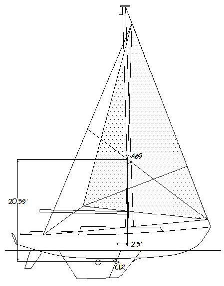
Figure 18 – Cal 40 rigged for cruising, sailing with genoa only. S/VBP results:
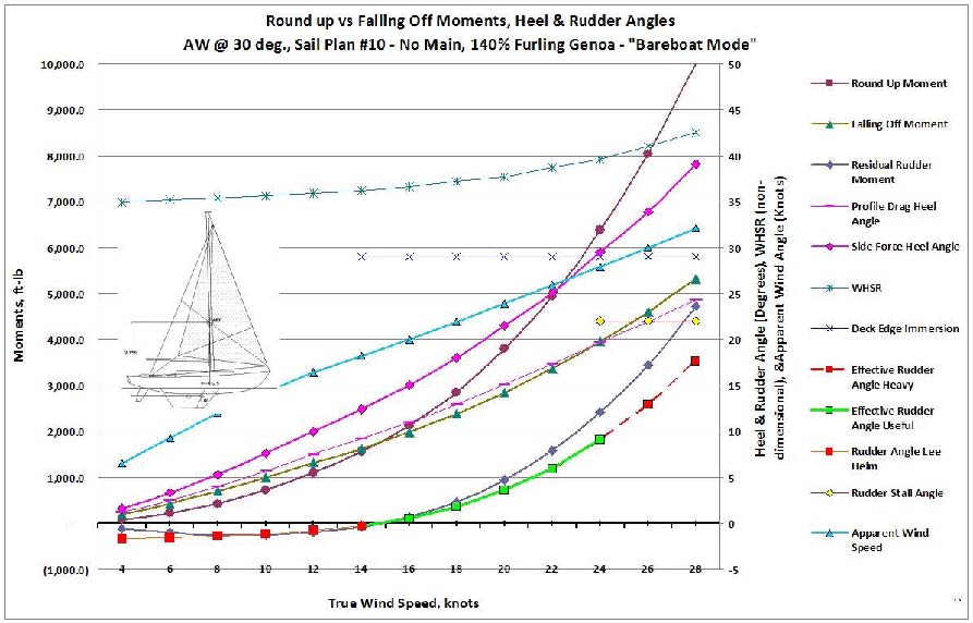
Figure 19 – S/VBP curves for the Cal 40 sailing in "Bareboat Mode."
A variation on this phenomenon, which has been much used for many years, is the sail combination "jib and jigger." On many ketches and yawls, sailing with the big jib alone may result in a neutral or slight lee helm, which is then corrected by setting the mizzen. Back when genoas weren't quite so big, this was a fairly effective way of shortening sail, or perhaps just sailing in a more relaxed fashion, especially with a midship awning on a hot sunny day.
CONCLUSION
The idea of using moments to determine balance is certainly not new. It has become clear from the forgoing, however, that simply using the traditional geometric methods, especially the profile sail area x profile wind force (or even a more precisely calculated side force, for that matter) times the basic geometric lead to get the falling off moment would give an erroneously high result, and therefore a false lee helm. The thrust has always been calculated correctly, as has the offset arm due to heel, but if it's balanced against an over-simplified falling off moment, then its value is sabotaged for purposes of determining balance.
The idea of showing the CEgs of the actual headsails rather than the foretriangle is also not new. Several sources have used actual headsail shapes for otherwise traditional balance discussions, as well as showing figures as to how the CEg moves fore and aft with different sail combinations. None would appear to have gone beyond this, though, and have spoken only generally of being careful with different combinations so as not to go out of balance. However, it would also appear that none have included the sheet positions as part of the geometry of establishing the CEg of headsails, something which now appears beneficial in establishing the sail's actual effect on the boat, especially when considering the falling off moment.
The approach proposed herein to predetermining sailing balance is meant to augment the traditional approach to lead that has been in practice for many years, and, indeed, is still a good conceptual starting point today when working up a new design in the early going. With the understanding that the many factors discussed above that have complicated the traditional approach have not changed, this proposed refined approach is similarly constrained to a certain degree of approximation. Any "improvements" generated by this particular proposal are, well, probably only that – improvements, refinements, adjustments. It is hoped, however, that these suggested procedures might a) be a useful tool for correcting existing balance problems and b) take at least some of the guesswork out of determining the proper shape of a boat's hull, and especially the arrangement of her appendages (also, by the way, fairly easily adjustable in the design process), her rig, and her complement of sails so as to achieve good sailing balance, particularly in the later stages of refining a design. And in time, perhaps some better agreement and narrowing of the often very wide ranges of suggested appropriate leads for a given genre of boats can be achieved.
Finally, it should be noted from the results graphs that, with too much sail in too much wind, the result is not only too much heel, but, just as dangerously, rapidly increasing weather helm. Professor Bruce Johnson, Captain Jan Miles, et.al. have been doing excellent work over the course of several papers (Miles et al, 2007; Johnson et al, 2009 and 2013) in confirming this fact from a shipboard measurement approach. While establishing the WHSR as a useful measure of stiffness, they are also confirming that efforts by a helmsman to fall off during a gust, especially when close reaching, are wholly ill-advised, not only because it prevents depowering when it's most necessary, but also because, as seen from the graphed results herein, increasingly excessive weather helm will simply not allow it.
ACKNOWLEDGEMENTS
Having another person ask just the right questions and get right to the kernel of a problem, all the while remaining positive and encouraging, is immeasurably helpful in putting together a project such as this. Professor Bruce Johnson was just that sort of mentor for this author, without whose help, insight and encouragement this effort would have fallen far short. My sincerest thanks to him.
REFERENCES
Baader, J., "The Sailing Yacht," W.W. Norton & Company, New York, NY, 1974.
Chapelle, H., "Yacht Designing and Planning," W.W. Norton & Company, New York, NY, 1936.
Claughton, A. & Pemberton, R., "Hull–Sailplan Balance, "Lead" for the 21st Century," 22nd International HISWA Symposium on Yacht Design & Yacht Construction, Amsterdam 2012.
Edmunds, A., "Designing Power & Sail," Bristol Fashion Pub., Enola, PA, 1998.
Gillmer, T. & Johnson, B., "Introduction to Naval Architecture," Naval Institute Press, Annapolis, MD, 1982.
Johnson, B., Lasher, W., Miles, J., Curry, W., "Uncertainties in the Wind-Heel Analysis of Traditional Sailing Vessels," Proceedings of the 21st Chesapeake Sailing Yacht Symposium, Annapolis, MD, March 12-13, 2013.
Keuning, J.A. & Vermeulen, K.J., "On the Balance of Large Sailing Yachts," 17th International HISWA Symposium on Yacht Design & Yacht Construction, Amsterdam 2002.
Keuning, J.A. & Vermeulen, K.J., "Keel–Rudder Interaction on a Sailing Yacht," 19th International HISWA Symposium on
Yacht Design & Yacht Construction, Amsterdam 2006.
Larsson, L & Eliasson, R., "Principles of Yacht Design," International Marine, Camden, Maine, 2000.
Marchaj, C.A., "Sailing Theory and Practice," Dodd, Mead & Company, New York, NY, 1964.
Milgram, J.H., "Sail Force Coefficients for Systematic Rig Variations," Technical & Research Report R-10, SNAME, September, 1971.
Skene, N., "Elements of Yacht Design," Sheridan House, Dobbs Ferry, NY, 2001.
www.blur.se/
, website, "Swedish Sailing and Racing," 2013. 
APPENDIX: